Pull a failed ESP and the diagnosis is usually straightforward after the fact. The motor overheated. The insulation broke down. The pump ran dry. The rods took a load they were not designed for.
What is far harder to reconstruct is when it started.
Overheating is not an event, it is a trend. Insulation does not fail, it degrades. A pump does not begin running dry at the moment it burns out. In almost every case there was an interval, often weeks long, in which the well was reporting the problem to nobody.
That interval is the entire value of downhole instrumentation. Not the sensors themselves, but the time between the first measurable deviation and the failure it leads to.
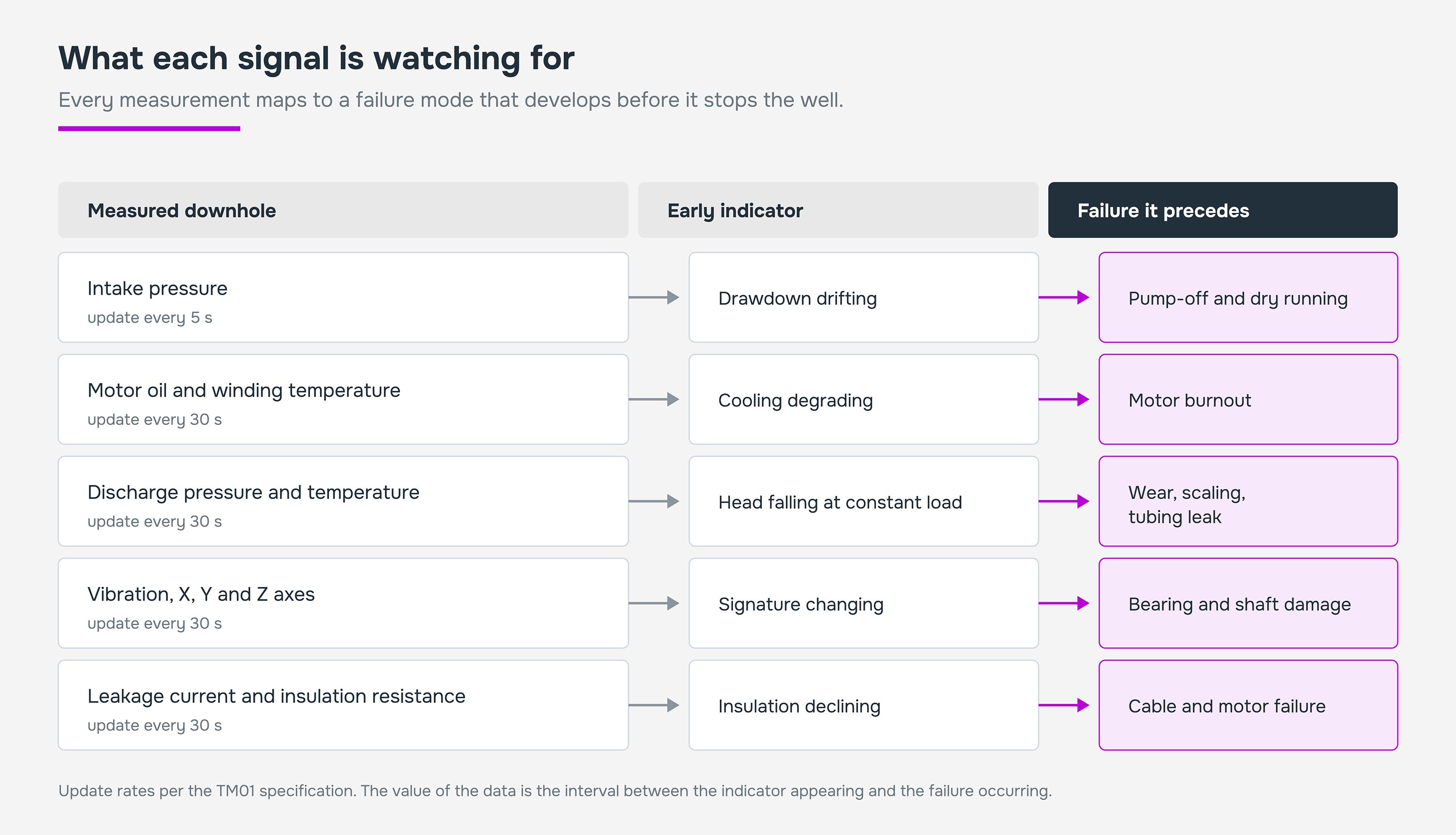
Figure 1. What each signal is watching for.
Why measurement rate and accuracy decide what you catch
Two specifications determine whether that interval is usable.
The first is update rate. The TM01 reports intake pressure every 5 seconds and every other parameter every 30. That is fast enough to see a pump-off event as it develops rather than to read about it in a log afterwards.
The second is accuracy, and it matters more than it appears. The TM01-20 and TM01-25 measure intake pressure to ±0.1% of full scale. The TM01-10 and TM01-15 measure to ±0.5%.
On a 0 to 40 MPa range, that is the difference between resolving a drawdown trend and watching it disappear into measurement noise. Building pressure recovery curves for well analysis needs the tighter figure.
That accuracy is a manufacturing claim, so it is worth knowing how it is established. Calibration runs on custom automated test benches, achieving ≤ ±0.05% FS on pressure and ≤ ±20 mK on temperature, with a 12-point calibration process on every unit except the TM01-15, which uses 7 points.
| Model | Configuration | Pressure accuracy | Fluid temperature | Calibration |
|---|
| TM01-20 | Single block, pump intake | ±0.1% FS | 0 to 150°C | 12 point |
| TM01-10 | Single block, pump intake | ±0.5% FS | 0 to 125°C | 12 point |
| TM01-25 | Dual block, adds discharge | ±0.1% FS | 0 to 150°C | 12 point |
| TM01-15 | Dual block, adds discharge | ±0.5% FS | 0 to 125°C | 7 point |
The dual-block models add a discharge unit at the pump outlet. Intake pressure alone tells you what the reservoir is delivering. Intake and discharge together tell you what the pump is doing with it, which is what separates a reservoir problem from an equipment problem.
Beyond ESP
The same principle extends across lift methods through the TM02, which instruments sucker rod pumps, progressive cavity pumps and gas lift.
Different failure modes, same logic: measure the parameter that moves first, and act while acting is still cheap.
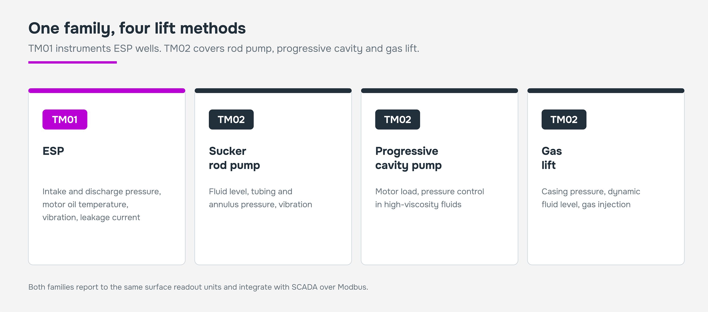
Figure 2. One family, four lift methods.
What the numbers in the title refer to
Triol states specific reductions for the TM02 by lift method. They are set out below as published, so you can see what each figure is attributed to.
| Lift method | Stated effect | Mechanism given in the catalog |
|---|
| Sucker rod pump | 30% reduction in failures | Pressure measurement in tubing and well detects leaks |
| Sucker rod pump | 40% prevention of rod breakage | Vibration and pressure monitoring catches excessive loads |
| Sucker rod pump | 40% reduction in clogging risk | Detects abnormal vibration and tubing pressure rise |
| Progressive cavity pump | 50% fewer gas-blockage failures | Maintaining optimal pressure reduces gas release |
| Progressive cavity pump | 60% fewer emergency shutdowns | Temperature and vibration reveal overloads in time |
| Gas lift | 50% fewer gas-blockage failures | Detects minor deviations in gas supply parameters |
| Gas lift | 60% fewer incidents from unstable inflow | Real-time parameter analysis |
These are the reductions the system is designed to deliver, by failure mode. What any individual well achieves depends on its own failure profile, on how the alarms are configured, and on whether anyone acts on them.
Instrumentation does not prevent failures on its own. It moves the decision earlier, and the value is in what gets decided.
Getting the data to where decisions happen
Measurement only counts if it reaches an operator.
Both families report to compact surface readout units that mount on a DIN rail, with a 3.5-inch display for live parameters and graphs, configurable protection thresholds, 30 days of event logging retrievable over USB, RS-232 and RS-485 wired interfaces, Wi-Fi for remote connection, and integration into SCADA over Modbus.
The TM01 surface card includes a built-in surge protector, and an IP66 enclosure option protects surface equipment on exposed sites.
The TM01 also supports notifications over the RS-485 digital channel when configured operating ranges are exceeded, which is what turns continuous measurement into an alert somebody actually receives.
Running ESP, rod pump, PCP or gas lift wells without downhole instrumentation, or with instrumentation nobody trusts?
Tell us the lift method, the well temperature and the motor configuration, and we will tell you which TM01 or TM02 configuration fits.
Request a configuration proposal for TM01 or TM02.